

| General Specifications | |
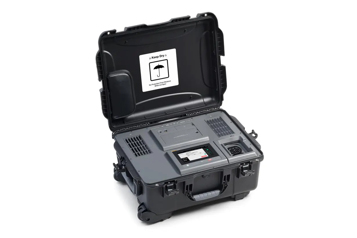
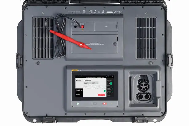
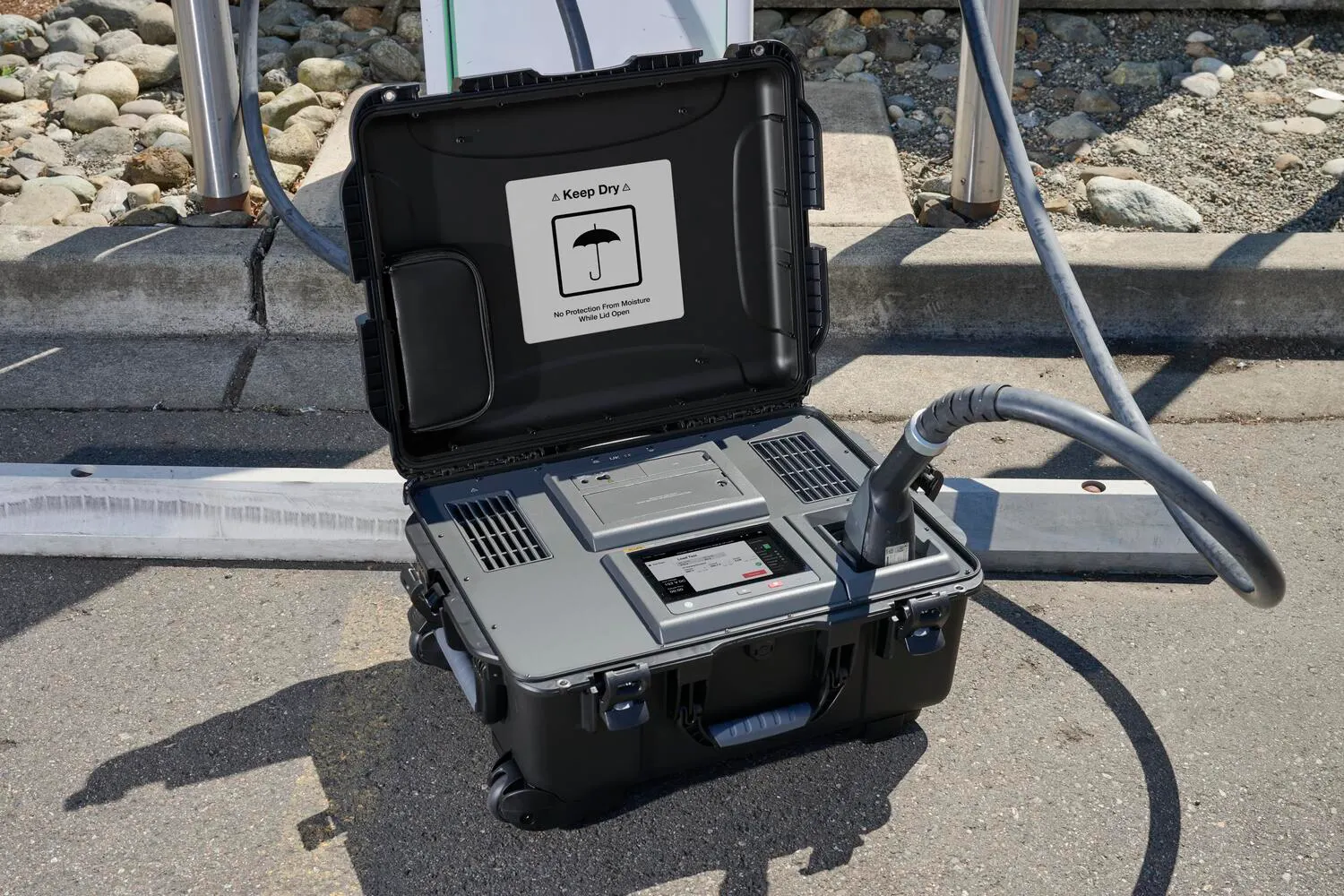
| Case | Rugged, wheeled hardcase |
| Dimensions | 65 cm x 50.8 cm x 30 cm (25.6 in x 20 in x 11.8 in) |
| Weight | 26 kg (57 lb) |
| Display | 7-in TFT, 1024 x 600 pixels, capacitive touch (operable with PPE gloves) Ultra-bright, sunlight-readable display with up to 1,700 cd/m² Brightness adjustment with ambient light sensor |
| Interface | Keys: Power on/off, Backlight, Stop Test LEDs: Power, Battery Status, Charging |
| Power | |
| Battery | Lithium-ion; 10.8 V, 6.8 Ah, 73.44 Wh (customer replaceable) |
| Runtime | 10 hours (battery recharges during test) |
| Charging Time | Typically 3 hours with USB-C PD 65 W charger |
| Backup Duration | Up to 6 months before recharge |
| Interfaces | |
| Wireless Connectivity | Integrated Wi-Fi (802.11b/g/n) and Bluetooth 5.2 module TX/RX Frequency Range: 2400 MHz to 2483.5 MHz Transmit Operating Power: < 100mW Encryption: WPA2-AES (WiFi), AES-CCM (Bluetooth) (Activation subject to firmware support. Refer to release notes for availability.) |
| USB-C | USB 2.0 high-speed for data download to PC-software TruTest™ and calibration Charging battery with USB-C power adapter PD 2.0 or higher with 9V 1.8 A USB-C flash drive support for firmware updates Max supply current: 900 mA |
| GNSS | Global navigation satellite receiver with internal antenna for time synchronization |
| Fuse | 11 A (not customer replaceable) |
| Warranty | Main unit: 2 years Battery and accessories: 1 year |
| Environmental Specifications | |
| Operating Temperature | -20 °C to +50 °C (-4 °F to +122 °F) |
| Battery Charging Temperature | 0 °C to +45 °C (32 °F to +113 °F) |
| Storage Temperature | -20 °C to +60 °C (-4 °F to +140 °F); Recommended: 0 °C to +30 °C |
| Operating Humidity | ≤100% up to 30 °C; 55% at 40 °C; 35% at 50 °C |
| Operating Altitude | Up to 3000 m |
| Storage Altitude | Up to 12,000 m |
| Vibration | IEC 60721-3-3 / 3M2 |
| Drop Test | 0.5 m (visual defects allowed) |
| Ingress Protection (lid closed) | IP54 |
| Ingress Protection (lid opened) | IP40 (protected against objects ≥1 mm) Air-cooling plenum: IP20 (protected against objects ≥12.5 mm) No protection against water ingress |
| Safety Standard | IEC 61010-1, Pollution Degree 2 IEC 61010-2-034 |
| Electrical Specifications | |||
| Auto-Test Sequence | |||
| Performed Tests | CCS Low-Level Communication and SLAC Test, Continuity Test, Insulation Resistance Test, Load Test (including Cable Check Voltage Measurement), IMD Test, Residual Voltage Test | ||
| Continuity Test (RLO) | |||
| Measurement | Test probe to PE pin of CCS 1/2 socket | ||
| Open-Loop Voltage | Max 5 V | ||
| Test Current | Max 10 A (up to 0.2 Ω) | ||
| Test Method | DC test with alternating polarity | ||
| Live Circuit Detection | Inhibits test if test probe voltage > 60 V | ||
| Test Probe Zeroing | Select ZERO in user interface to zero the test probe resistance. | ||
| Standard | IEC61557-4 | ||
| RLO Range | Resolution | Accuracy | |
| 2 Ω | <1Ω: 0.1 mΩ ≥1Ω: 0.0001Ω | ≤ 20 mΩ: ± (8% + 0.8 mΩ) ≤ 200 mΩ: ± (4% + 4 mΩ) > 200 mΩ: ± (4% + 40 mΩ) | |
| Insulation Resistance (RISO) | |||
| Measurements | Insulation Resistance DC+ to PE and DC- to PE | ||
| Test Voltage | Max EVSE Voltage ≤ 500 V: 500 V +10% / -0% Max EVSE Voltage > 500 V: 1000 V +10% / -0% | ||
| Max Short Circuit Current | 2 mA | ||
| Standard | IEC61557-2 | ||
| Test Voltage | RISO Range | Resolution | Accuracy |
| 500 V | 10 kΩ to 20 MΩ | 0.01 MΩ | ± (5 % rdg + 2 digit) |
| 1000 V | 10 kΩ to 20 MΩ | 0.01 MΩ | ± (5 % rdg + 2 digit) |
| CCS Communication Test - Control Pilot (CP) | |||
| Parameters | Voltage CP high, Voltage CP low, Frequency, Duty Cycle | ||
| Simulation of states | A, B, C, D, E (simulation and validation) | ||
| Digital Protocol | DIN SPEC 70121, ISO 15118 | ||
| Parameter | Range | Resolution | Accuracy |
| CP High, CP Low | -15 V to +15 V | 0.01 V | ± (0.4 % rdg + 2 digit) |
| Frequency | DC, 900 to 1100 Hz | 1 Hz | 0.1 % rdg or 1 digit |
| Duty Cycle | 2 to 98 % | 0.10% | ± 5 digit |
| SLAC | 0 dB to 20 dB | 1 dB | |
| CCS Communication Test - Proximity Pilot (PP) | |||
| Parameter | Range | Resolution | Accuracy |
| PP Resistor | 50.0 to 499.9 Ω | 0.1 Ω | ± 0.5 % |
| 500 to 5000 Ω | 1 Ω | ||
| Load Test | |||
| Parameters | Cable Check Voltages: VDC+ to PE, VDC- to PE Load Test: Voltage DC+ to DC-, Current, Power, Duration | ||
| Parameter | Range | Resolution | Accuracy |
| Voltage | 1000 V | 0.1 V | ± (0.2 % rdg + 4 digit) |
| Current | 10 A | 0.01 A | ± (0.5% rdg + 5 digit) |
| Power | 0 to 3.75 kW | 0.001 kW | ± (0.7% rdg + 15 digit) |
| Insulation Monitoring Device (IMD) Test | |||
| Auto-Test | No trip test, trip test Test Resistor no trip test: 250 kΩ (DC+ to PE) Test Resistor trip test: 95 kΩ (max. EVSE Voltage >500 V dc), 45 kΩ (max. EVSE Voltage ≤500 V dc) (DC- to PE) Duration: max 15 s for each test | ||
| Test Resistor Range | 19.5 kΩ to 3 MΩ, 256 values | ||
| Standard | IEC61557-8 / IEC 61557-18 | ||
电 话:173-0381-6163
传 真:+86-0371-69082289
手 机:173-0381-6163
邮 箱:1654991910@qq.com
地 址:郑州市中原区陇海西路300号3-2-2602室